WebRTC-to-SIP Gateway Architecture: Components, Translation, and Deployment Patterns

A WebRTC-to-SIP gateway is the network element that lets a browser-based voice or video application reach the PSTN, a SIP trunk, a PBX, or any external SIP peer. It sits at a boundary where two real-time communication stacks that disagree on signaling, transport, encryption, NAT traversal, and identity have to share a call.
The companion article WebRTC vs SIP: Differences and Use Cases covers what each technology is and when to choose one. This piece assumes that background and looks one layer deeper: the subsystems a gateway is built from, how each translation works on the wire, and how the components fit together in a production deployment. For the SIP-side protocol mechanics this article assumes you are familiar with, SIP Signaling Fundamentals and SIP Call Flow Explained Step by Step are the companion references.

What the WebRTC-to-SIP Gateway Actually Has to Do
A WebRTC PeerConnection and a SIP dialog look similar from a thousand feet: both negotiate a media session between two endpoints, both carry encrypted RTP, both run over UDP. From close up, they barely overlap. A gateway has to solve five translation problems at the boundary, and each one needs its own subsystem.
Signaling translation maps the application’s signaling on the WebRTC side (typically WebSocket carrying SIP-over-WebSocket or a proprietary JSON protocol) to standard SIP on the carrier side.
NAT traversal termination receives ICE candidates on the browser leg, presents a single static address on the SIP leg, and runs STUN/TURN infrastructure for the WebRTC side.
Media encryption translation terminates DTLS-SRTP toward the browser and re-keys the media on the SIP leg using whatever the peer expects: SRTP via SDES, DTLS-SRTP again, or plain RTP.
Codec mediation handles the gap between Opus (the WebRTC default) and G.711 or G.729 (the SIP defaults), either through SDP negotiation or active transcoding.
Identity bridging asserts an identity on the outbound SIP leg that downstream systems can act on (caller ID, STIR/SHAKEN signing), because WebRTC has nothing at the protocol layer to carry forward.
The rest of this article walks through each of these subsystems and then puts them back together in the deployment topologies that actually appear in production.
Signaling Translation
WebRTC has no defined signaling protocol. The application picks one. In practice, two patterns dominate.
SIP-over-WebSocket (RFC 7118)
This path runs the SIP protocol itself across a WebSocket connection between the browser and the gateway. The browser uses a JavaScript SIP library (JsSIP, SIP.js); the gateway terminates the WebSocket, parses the SIP stack on top, and re-encodes the same messages on a normal UDP, TCP, or TLS SIP socket toward the carrier. The translation is structurally simple because both sides speak SIP; only the transport changes. Kamailio (with the websocket module), OpenSIPS, and Janus in SIP gateway mode all implement this pattern.
Proprietary JSON over WebSocket
This is what most application-layer SDKs use, including Twilio Programmable Voice, Vonage, Zoom Phone, and custom CPaaS stacks. The browser sends messages like {"type": "invite", "callee": "...", "sdp": "..."} and the application backend translates them into SIP internally. The gateway in this case is part of the backend itself, and the SIP boundary is internal to the platform.
What signaling translation has to handle that SIP does not
SDP munging covers the differences between the SDP a browser produces and the SDP a carrier expects. The browser’s offer lists every ICE candidate it discovered, declares mandatory DTLS-SRTP, and advertises Opus. The carrier expects an SDP without ICE attributes, with SDES keys (or plain RTP), and a different codec list. The gateway rewrites the SDP fully on each leg, presenting one shape to the browser and another to the carrier.
Trickle ICE matters because WebRTC discovers ICE candidates asynchronously and sends them to the peer as they appear, after the initial offer. The gateway has to accept these trickled candidates, but SIP has no equivalent mechanism, so the SIP-side offer either waits for ICE to complete (end-of-candidates) or omits ICE entirely and uses a single static address.
Re-INVITE handling becomes a translation problem because mid-call changes (hold, mute, codec change, transfer) arrive as renegotiation on both sides but in different shapes. The gateway has to map between them without dropping the call. See SIP Call Flow Explained for how re-INVITE works on the SIP side.
NAT Traversal and ICE Termination
WebRTC assumes the endpoints will solve NAT themselves. SIP assumes the network operator will. The gateway has to bridge both philosophies, which it does by running full ICE on one leg and no ICE on the other.
On the browser leg, the gateway runs full ICE. It advertises its own ICE candidates (host, server-reflexive via STUN, relayed via TURN), tests connectivity against the browser’s candidates, and picks the best path. If direct paths fail, the gateway’s own TURN server relays the media. This means the operator has to deploy and scale TURN infrastructure proportional to the WebRTC traffic; in deployments where most browsers sit behind restrictive corporate NAT, TURN can carry a meaningful share of media bytes.
On the SIP leg, the gateway presents a single static IP and port to the carrier. There is no ICE on this leg; the carrier expects a fixed RTP socket on the gateway’s public address. The gateway is responsible for keeping that socket reachable through whatever NAT or firewall sits in front of it, which is the same problem any SBC solves with topology hiding and far-end NAT handling.
The asymmetry is by design. ICE pushes complexity into the endpoints when both are smart (two browsers). At a carrier boundary, where one side is a hardware switch that has not changed in fifteen years, the gateway absorbs the complexity instead.
Media Encryption: The DTLS-SRTP Handoff
This is the most cryptographically interesting part of the gateway. The two legs use different key exchange mechanisms, and the gateway is the trust boundary between them.
On the browser leg, the gateway acts as the DTLS responder. After ICE picks a path, the browser initiates a DTLS handshake on the same UDP socket the media will travel over. The gateway presents a certificate (self-signed is acceptable; the fingerprint travels in the SDP), completes the handshake, and derives the SRTP master keys from the DTLS session keys via the export_keying_material API. Media flowing from the browser is encrypted with those keys.
On the SIP leg, the gateway negotiates SRTP differently. The most common pattern is SDES, where the master key is embedded directly in the SDP body and the body is protected by TLS on the signaling channel. Less commonly the SIP peer also speaks DTLS-SRTP, in which case the gateway runs a second DTLS handshake outbound. The least secure pattern is plain RTP, where no encryption is negotiated at all; the gateway encrypts the browser leg and decrypts on the SIP leg.
Whichever combination applies, the gateway holds two independent SRTP contexts at the same time and re-encrypts every packet as it crosses the boundary. The packets themselves change: SSRC values are rewritten, sequence numbers are reset, and the keys are completely different on each side. There is no key sharing across the legs; that is the entire point.
Codec Mediation and Transcoding Placement
Opus is the WebRTC default. G.711 (mu-law or A-law) is the PSTN default. The gateway has three options when a call crosses the boundary.
Negotiate a common codec. If the carrier supports Opus on the SIP trunk (most do not) and the browser supports G.711 (most do), the gateway can pass through without transcoding. Some MSP and CPaaS deployments configure this to avoid the transcoding cost entirely.
Transcode. The gateway decodes the inbound RTP, re-encodes as the outbound codec, and forwards the new stream. Opus-to-G.711 is the common case. For an extended view of how transcoding works at the SBC edge, the SBC AMR to G.711 Transcoding article walks through the same decode/re-encode loop for mobile-network codecs.
Reject the call. If neither side can negotiate something the other accepts (rare but possible with G.729-only trunks), the gateway returns 488 Not Acceptable Here.
Where transcoding lives in the gateway architecture has practical consequences. Software transcoding on commodity CPUs is fine for G.711 to G.711 (A-law to mu-law is essentially free) and for limited Opus capacity. High-density Opus-to-G.711 transcoding is dominated by DSP arithmetic, and most carrier-grade deployments offload this work to dedicated hardware to keep CPU headroom available for the rest of the gateway’s responsibilities.
For an SBC sitting on the SIP-facing leg of a two-tier deployment, the right placement is usually to keep G.711 transcoding in software (A-law to mu-law is supported natively in ProSBC) and offload AMR and G.729 to a hardware transcoding unit such as TSBC-HW-TRANS. The codec on the WebRTC inbound leg is the one that drives the DSP requirement, not the SIP-side codec.
Identity Bridging
WebRTC has no protocol-layer identity. The application asserts identity in its own backend, usually with a login token tied to a user account. When that call crosses to SIP, the carrier needs something concrete to put in the From header, the P-Asserted-Identity header, and (in the US) the STIR/SHAKEN Identity header.
The gateway solves this by mapping the WebRTC user identity to a SIP identity at the boundary. The gateway is configured with a SIP trunk identity (a service number, a DID range, or a B2BUA-asserted identity) and stamps the outbound INVITE with that identity, plus per-call attestation that the gateway has authenticated the user upstream.
For STIR/SHAKEN, the gateway can sign at attestation level A only when it is operating as the originating carrier. If the gateway hands off to a carrier that signs, the gateway provides the originating identity and the carrier’s signing service produces the Identity header. ProSBC integrates with TransNexus ClearIP and Neustar over SIP for this exact pattern: the gateway routes the call to a NAP whose service_type is AUTHENTICATION, ClearIP returns a 302 with the Identity header attached, and the call advances to the carrier. The mechanics of normalizing identity-bearing headers across vendor SIP dialects are covered in SIP Header Manipulation.
What cannot be bridged: WebRTC identity tokens (JWTs, OAuth flows) do not survive the SIP boundary. Whatever trust the application backend established is exchanged for the gateway’s own trust relationship with the carrier.
Deployment Topologies
Three patterns dominate in production. The choice depends on scale, on whether the deployment needs multi-party conferencing, and on whether the operator wants one element doing everything or specialized elements doing one job each.
Single-tier gateway
A single device terminates the WebRTC side, performs the translation, and presents a SIP interface to the carrier. Janus with the SIP plugin, Kamailio with the websocket and rtpengine modules, and several CPaaS-vendor appliances follow this pattern. The advantage is operational simplicity: one box to scale and monitor. The disadvantage is that the gateway has to do everything, including DSP-heavy transcoding and the carrier-side SBC work (header manipulation, fraud protection, topology hiding, registrar absorption). At small scale this is acceptable; at carrier scale it consolidates too much responsibility into one element.
Two-tier: WebRTC gateway in front of an SBC
This is the more common production pattern. A dedicated WebRTC gateway handles the browser-facing leg: WebSocket termination, ICE, DTLS-SRTP, TURN, ICE candidate trickling, and identity assertion from the application backend. The gateway then hands off a normalized SIP session to an SBC that handles the carrier-facing leg: SIP over TLS, SRTP with SDES, header normalization, topology hiding, call admission control, fraud scoring, and STIR/SHAKEN integration. The split lets each element specialize and scale independently of the other.
ProSBC fits this pattern on the SIP-facing side. It is not a WebRTC-facing gateway and does not terminate WebSocket signaling; the WebRTC gateway in front of it (Janus, Kamailio, OpenSIPS, or a CPaaS application server) handles the browser side. ProSBC handles everything downstream: TLS for SIP signaling, SRTP for media (relay or RTP-to-SRTP conversion), per-trunk-group SIP header manipulation to match what each carrier expects, topology hiding between the WebRTC zone and the carrier, and integration with fraud detection and STIR/SHAKEN partners.
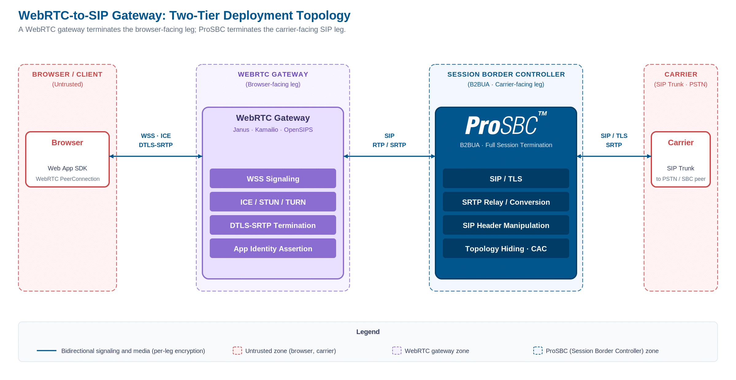
Two-tier deployment topology: a WebRTC gateway handles the browser-facing leg (WebSocket signaling, ICE, DTLS-SRTP, TURN), then hands a normalized SIP session to ProSBC, which handles the carrier-facing leg (SIP/TLS, SRTP, SIP header manipulation, topology hiding, fraud and STIR/SHAKEN integration). Click to enlarge.
Three-tier with a media server
For deployments that need multi-party conferencing, an SFU (Selective Forwarding Unit) or MCU (Multipoint Control Unit) sits between the browser and the gateway. The SFU handles the conference processing (video stream forwarding to all participants and audio stream mixing between participants), and the gateway bridges the SFU’s SIP output to the carrier when the conference includes a PSTN participant. This is the architecture behind dial-in conferencing for most large meeting platforms and contact center deployments.
The three-tier pattern adds an SFU between the browser cluster and the WebRTC gateway, with the rest of the SIP path unchanged.
Scaling: TURN, Signaling, and Media
Each subsystem scales on a different axis, and capacity planning for one does not tell you much about capacity planning for another.
TURN bandwidth is the most variable line item. A direct browser-to-gateway path uses zero TURN bandwidth. A browser behind a symmetric NAT or a restrictive corporate firewall relays through TURN for the entire call duration, and the TURN server pays for the bytes in both directions. Plan TURN capacity for the worst-case fraction of users who cannot find a direct path, not the average. In deployments with significant enterprise traffic, that fraction is regularly above 20 percent.
Signaling capacity on the gateway is bound by WebSocket connection density, not message throughput. Each connected browser holds an open WebSocket; tens of thousands of idle WebSockets on a single host is plausible if memory is provisioned correctly. The signaling translation itself is cheap per message but the long-lived connections dominate.
Media capacity scales with the transcoding load on a per-call basis. Pure relay (no transcoding, both sides on the same codec) scales close to network line rate. Opus-to-G.711 transcoding is constrained by DSP cycles or CPU; published density for hardware transcoders runs into the thousands of concurrent sessions per media processing server, while software transcoding is typically a fraction of that.
For the SIP side, ProSBC handles up to 60,000 concurrent signaling sessions per server with software transcoding for G.711 only; AMR and G.729 require a hardware transcoding unit. Mixing the two cleanly is what lets a two-tier deployment scale the media plane independently of the signaling plane: the WebRTC gateway sizes for WebSocket density and TURN throughput, while the SBC sizes for SIP sessions and (when present) transcoding units.
High Availability and Observability
A WebRTC-to-SIP gateway sits in the critical voice path, which means every component needs a redundant peer and the failure modes need to be visible from both sides.
For HA, the WebRTC gateway can run active-active behind a load balancer because WebSocket connections are independent and stateless from the perspective of the cluster. The TURN servers are typically active-active behind anycast or DNS round-robin. The SBC on the SIP leg is more often active-standby with a virtual IP. ProSBC supports 1+1 HA in active-standby for maximum uptime, with the caveat that failover is not zero-loss; some in-flight calls drop during the cutover, and the deployment should be designed to retry them quickly rather than to prevent the drop.
For observability, traceability across the legs is the hard problem. A call that fails between a browser and a PSTN destination touches the application backend, the WebRTC gateway, the SBC, and the carrier; each component logs in its own format, and correlating a single call across all of them requires propagating a call identifier through every hop. The standard practice is to inject a unique identifier as a SIP header on the SIP leg and a custom field in the application’s signaling on the WebRTC leg, then surface both in centralized logging.
ProSBC exposes per-NAP and per-call metrics (CPS, ASR, ABR, PDD, jitter) through its REST API and can route these into a customer’s observability platform of choice. VoIP monitoring best practices covers what those metrics mean and which thresholds matter in a production voice deployment.
Frequently Asked Questions
Can a single SBC terminate both WebRTC and SIP, removing the need for a separate WebRTC gateway?
Some SBCs include WebRTC-facing modules (a built-in SIP-over-WebSocket listener, ICE/DTLS-SRTP support, a small TURN). ProSBC does not. The standard production pattern with ProSBC is two-tier: a WebRTC gateway (Janus, Kamailio, OpenSIPS, or a CPaaS application server) handles the browser-facing leg, and ProSBC handles the SIP-facing leg toward the carrier. The split is also useful operationally because the two sides have very different scaling profiles.
Do I need a TURN server if my browsers are on the same corporate network as the gateway?
Usually yes. ICE will discover direct paths within the private network when they exist, but corporate firewalls often restrict outbound UDP or apply asymmetric NAT that defeats direct candidates. A TURN server gives ICE a fallback that works through almost any restrictive network, at the cost of relaying media bytes through the TURN host.
What is the difference between DTLS-SRTP and SDES?
DTLS-SRTP performs the key exchange on the media path itself, using a DTLS handshake to derive the SRTP master keys. SDES embeds the master keys in the SDP body of the SIP signaling, relying on TLS-protected signaling for confidentiality. WebRTC mandates DTLS-SRTP; SIP supports both and historically uses SDES more often. The gateway terminates DTLS-SRTP toward the browser and re-keys with whatever the SIP peer requires.
Is transcoding always required at the WebRTC-to-SIP boundary?
Not always. If both sides negotiate a common codec (some modern SIP trunks support Opus, and most browsers can encode G.711 and G.722), the gateway can relay the codec through without re-encoding. Where the two sides cannot agree, transcoding is required, and the gateway has to be sized for the worst case if calls are routed across heterogeneous carriers.
How is identity carried from a WebRTC user to a STIR/SHAKEN-signed SIP call?
The WebRTC application backend authenticates the user upstream; the gateway is configured with a SIP trunk identity tied to that user (a DID, a service number) and stamps the outbound INVITE accordingly. STIR/SHAKEN signing happens at the carrier or the SBC integrated with a signing service, not in the browser. The Identity header is added on the SIP side after the WebRTC-to-SIP translation is complete.
Conclusion
A WebRTC-to-SIP gateway is the boundary element that lets two real-time stacks share a call without either side knowing about the other’s protocol decisions. The gateway is built from five subsystems: signaling translation, ICE termination, DTLS-SRTP re-keying, codec mediation, and identity bridging. Each one has its own scaling profile, and the most common production deployment splits them across two tiers: a dedicated WebRTC gateway on the browser-facing side and an SBC on the carrier-facing side, so each element specializes in the work it does best.
When evaluating gateway components for a production deployment, the questions to ask are: which side does each element terminate, where does transcoding live (hardware or software), how are TURN and signaling capacity sized independently, and how does identity get carried across the boundary into STIR/SHAKEN signing. The answers determine whether the deployment is a single-tier appliance, a two-tier split, or a three-tier conferencing topology.
Bridge WebRTC and Carrier SIP with ProSBC
ProSBC is a software B2BUA that handles the SIP-facing leg of any WebRTC-to-SIP deployment. The WebRTC gateway (Janus, Kamailio with the websocket module, OpenSIPS, or a CPaaS application server) sits in front of it and terminates the WebSocket signaling, ICE, and DTLS-SRTP. ProSBC takes the normalized SIP session from the gateway and applies everything the carrier or PBX side needs: TLS for SIP signaling, SRTP for media (relay or RTP-to-SRTP conversion), per-NAP SIP header manipulation, topology hiding, call admission control, dynamic blacklisting, and STIR/SHAKEN integration over SIP with TransNexus ClearIP or Neustar.
For deployments that need Opus-to-G.711 transcoding at the SIP boundary, ProSBC pairs with TSBC-HW-TRANS, a hardware transcoding unit. ProSBC by itself handles G.711 A-law to mu-law transcoding in software; Opus, AMR, and G.729 require the DSP hardware.
ProSBC runs on AWS, Azure, VMware, KVM/Proxmox, or bare metal, with per-trunk-group transport and crypto configuration that matches the WebRTC gateway upstream and the carrier downstream independently.
Prefer to evaluate on your own first? Start your 30-day free trial.